CARPAL TUNNEL
Specialized projection for evaluation of the carpal tunnel and median nerve compression

Demonstrated Pathology
This projection allows for:
- Ruling out calcifications and bony changes of the carpal sulcus/tunnel
- Identifying impingement on the median nerve
- Visualizing fractures of the hamate (hook), pisiform, and trapezium
- Evaluating the bony structure of the carpal tunnel
- Detecting carpal tunnel stenosis
- Identifying bony causes of carpal tunnel syndrome
Exposure Factors
Moderate for good bony penetration
Low exposure
Optimal parameters: Configured for detailed carpal tunnel visualization
Carpal Tunnel Anatomy
The carpal tunnel is an osteofibrous canal formed by:
- Base: Carpal bones in an arched arrangement
- Roof: Transverse carpal ligament (flexor retinaculum)
- Contents: Median nerve and flexor tendons
- Dimensions: Approximately 2.5 cm long
- Function: Protects neurovascular structures
This projection is specifically designed to evaluate the bony component of the tunnel.
Visible Anatomical Structures
The following should be clearly observed:
- Carpal arch formed by carpal bones
- Carpal tunnel in axial view
- Hamate and pisiform without superimposition
- Trapezium and trapezoid
- Scaphoid and lunate
- Proximal metacarpals
- Carpal joint spaces
Image Receptor Size and Orientation
Transverse orientation: To include the entire wrist and distal forearm
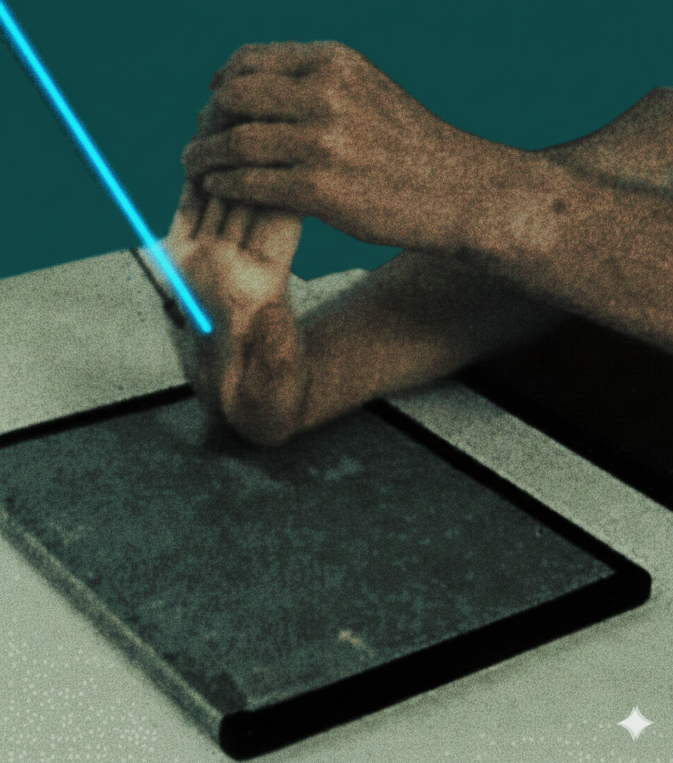
Patient Positioning
Purpose of 10° internal rotation: To separate the pisiform from the hamate for optimal visualization
Specific Central Ray Angulation
Direction: Angled 25° towards the long axis of the hand
Target: 3 cm distal to the base of the third metacarpian (palmar center)
Purpose: Optimal axial projection of the carpal tunnel
Central Ray Specifications
Direction: Towards the long axis of the hand
Angle: 25° from perpendicular
Target: 3 cm distal to base of third metacarpal
Center: Palmar center of the hand
Optimal Image Characteristics
Visible Tunnel
Carpal tunnel clearly visible
Carpal arch well defined
No superimposition of pisiform-hamate
Joint Spaces
Carpal spaces open
Joints well defined
No structure compression
Specific Bones
Hamate and pisiform separated
Trapezium visible without rotation
Scaphoid in adequate position
Instructions to the Patient
"Stay still during exposure"
Maintain hyperextension position without moving during the radiographic exposure
Notify the technician if the position causes excessive pain or discomfort
Acceptable Image Criteria
Carpal Arch
Tunnel clearly visible
Bony Separation
Pisiform-hamate separated
No Rotation
Correct anatomical axes
Hyperextension
90° relative to forearm
Common Technical Challenges
Frequent problems in carpal tunnel projection:
- Insufficient hyperextension of the wrist
- Incorrect internal rotation (not 10°)
- Pisiform-hamate superimposition
- Incorrect central ray angulation (not 25°)
- Movement during exposure
- Uncomfortable position that the patient cannot maintain
- Incorrect centering of the ray
- Inadequate exposure for bony visualization
Solution: Ensure maximum 90° hyperextension and precise 10° internal rotation
Specific Clinical Indications
IMPORTANT CONSIDERATIONS
This projection requires maximum wrist hyperextension
- Do not perform in cases of acute fracture or instability
- Evaluate patient tolerance to hyperextension
- Consider limitations due to severe arthritis or contractures
- In patients with severe pain, consider alternatives
The position may be difficult to maintain for some patients; ensure comfort and stability.